Checking HVI systems
For safety during installation, approval and maintenance tests: Use the test report as a practical guide for the setting up of lightning protection systems and our services for assessing the function and condition of HVI Conductors.
Documents required for the inspection
The following documents must be available for checking an HVI system:
- General system documentation
- Documents for planning the LPS (Lightning Protection System)
- Separation distance calculation
- Installation instructions, valid at the time of installation
Prescribed test intervals
The required test intervals come from the normative specifications in IEC 62305-3 section D.7.2.2. The protection class determines the test intervals. There are exceptions after a lightning strike or structural changes, which shorten the intervals. An HVI system may only be tested by qualified, trained specialist personnel.
Criteria for the visual inspection
The visual inspection of the HVI Conductors is carried out from the supply point to the connection to the LPS (Lightning Protection System) or the earthing system. The following criteria, among others, must be checked:
I. Supporting tube
- Installation locations: were the supporting tubes installed outside Ex zone 1/21?
- Was the sealing end range of the supporting tube maintained (metal-free volume – cylinder)?
- In what condition is the shrinking of the connection elements?
- Was the aluminium tube connected to the nearest point of the system's equipotential bonding?
II. Horizontal / vertical cable routing
- Is there damage to or damage points on the HVI sheath?
- Were the permissible bending radii complied with?
- Was the minimum distance between cables routed in parallel (distance > 200 mm) maintained?
- How was the sealing end designed for connection to parapets or ring conductors?
Complete inspection
The complete inspection is carried out at different regular intervals depending on the lightning protection class or local conditions such as Ex zones or corrosive atmospheres. The difference between a visual inspection and a complete inspection is that an additional measurement is recommended for the latter: In a meshed HVI system, a loop measurement is used to check whether a low-impedance continuity (recommended value < 1 Ohm) is present.
HVI check: simple function and status determination of the HVI Conductors
Both the 1-kV and 15-kV measuring methods can be used to reliably detect both mechanical and electrical damage to HVI Conductors; e.g. holes or electrical breakdown as a result of overloads.
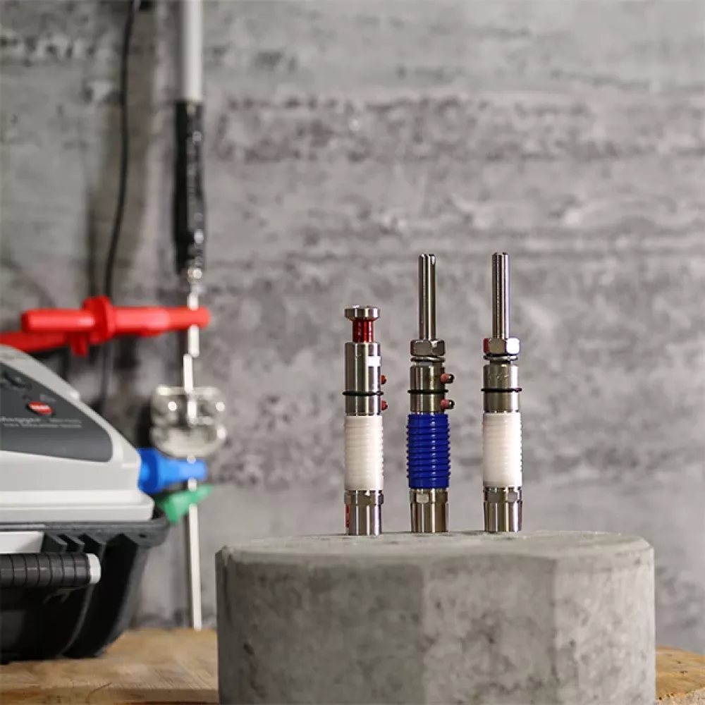
In addition to the two measuring methods, HVI check also includes testable / insulated connection elements, insulating caps, tools and clamps. The test is to be carried out with a commercially available insulation measuring device.


Watch now:
Installation of HVI check
Watch now:
Insulation measurement of HVI check
More information on HVI Lightning Protection
Find out more about HVI Lightning Protection and what to bear in mind when it comes to separation distances.
With the high-voltage-resistant, insulated cables of the HVI systems, you can maintain separation distances without complication. The HVI (High Voltage Insulation) Conductor safely discharges lightning current from the air-termination system to the earth-termination system.
Maintaining the separation distance prevents dangerous flashovers between earthed parts of the building and the lightning-current-carrying components of the lightning protection system.
Downloads
HVI Check
Dielectric withstand test for HVI Conductors
Test Instructions
Dielectric withstand test on high-voltage-resistant, insulated down conductors
Test report
HVI Lightning Protection system inspection
Installation instructions
HVI light plus – insulated connection elements
FAQ
- An HVI system is an electrically insulated external lightning protection system in accordance with DIN EN IEC 62305-3. The minimum requirements set out in section 7 must therefore be met for testing. Regulatory requirements, the specifications of property insurers or technical standards (e.g. DIN EN IEC 62305-3, Supplement 3 *)) must also be taken into account with regard to the type and frequency of tests, where applicable.
*) DIN EN IEC 62305-3, Supplement 3 is due to be published in October 2026. Until the publication of this Supplement, the inspection intervals specified in DIN EN 62305-3, Supplement 3:2012-10 should be used.
According to Table 1 DIN EN 62305-3 Supplement 3 (VDE 0185-305-3 Supplement 3):2012-10:
For lightning protection systems in protection classes I and II, a visual inspection is required annually and a comprehensive inspection every two years. In critical situations, a comprehensive inspection must be carried out annually.
For protection classes III and IV, a visual inspection is required every two years and a comprehensive inspection every four years; in critical situations, a comprehensive inspection must be carried out annually.
For comprehensive inspections in critical situations:
a) Lightning protection systems for structures at risk of explosion should be visually inspected every six months. Metrological testing of the installation should be carried out once a year. To understand seasonal fluctuations, it is acceptable to take measurements at 14- or 15-month intervals, thereby determining the earth contact resistance at different times of the year.
b) Critical situations may relate to structures containing sensitive systems, or to office buildings, commercial premises or public squares where large numbers of people may gather.
- DIN EN IEC 62305-3 does not specify clear inspection intervals. The intervals depend on certain factors, such as the use of the structures, the materials used, and the local environment (e.g. installations with potentially explosive atmospheres) and ground conditions.
- In addition to the specified inspection intervals, a lightning protection system should always be inspected whenever significant modifications or repairs have been carried out, or following a recorded lightning strike.
A visual inspection shows whether
- the entire system is consistent with the technical documentation;
- the complete external and internal lightning protection system is in good condition;
- there are no loose connections or interruptions in the conductors of the lightning protection system;
- no parts of the system have been significantly weakened by corrosion, particularly at ground level;
- all visible earth connections are in good working order;
- all visible conductors and system components are secured to the mounting surfaces, and components providing mechanical protection, such as spacers and supporting tubes, are in working order and correctly positioned;
- the installation instructions (assembly guidelines) of the manufacturers have been followed;
- no changes have been made to the protected structure that require additional protection measures;
- separation distances are maintained;
- measuring points are clearly assigned (e.g. by means of identification labels) to ensure the reproducibility of the measured values.
Following the acceptance test, the lightning protection system must be inspected at regular intervals to ensure it is in good working order. The comprehensive inspection includes a review of the documentation, a visual inspection and an electrical test, in accordance with the manufacturer's specifications applicable the time of installation.
Regular, comprehensive inspections are essential to ensure the long-term effectiveness of a lightning protection system (e.g. HVI system).
In addition to a continuity test (recommended value < 1 Ω), the electrical testing of a HIL system can also include a dielectric withstand test. This should be taken into account during the design stage. If these tests are not carried out, or cannot be carried out, this must be noted in the test report.
HVI check can be used to detect both mechanical and electrical damage to HVI Conductors that cannot be identified during a visual inspection, such as damage to the insulation behind a façade.