HVI Lightning Protection
Flexibility and maximum safety: Using the high-voltage-resistant, electrically insulated HVI Conductors from DEHN, you can easily maintain separation distances. The possible uses of HVI Conductors are extremely diverse and suitable for every application. Only DEHN offers such a wide range and over 20 years of experience in insulated lightning protection.
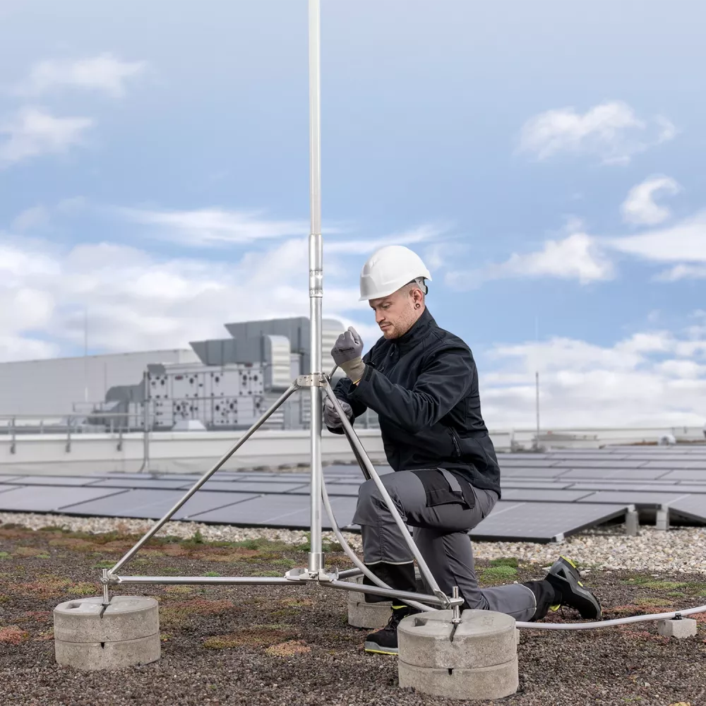
Innovative HVI Conductors: Safety and design in perfection
The HVI (High-Voltage Insulation) Conductors developed by DEHN have a lightning-current-carrying core that is sheathed with insulating material. The required separation distances from other conductive parts of the building or electrical wiring and pipes are maintained without having to take any further measures.
HVI Conductors can also be installed behind the façade and can even be painted in the same colour as the building. For you, this means: optimum adaptation to the building architecture and many design options.
Types of conductor
The high-voltage-resistant, insulated conductors ensure that the separation distance to electrically conductive components is maintained. The range comprises four variants: HVI light plus, HVI and HVI power.
When selecting the right conductor, the necessary separation distance is crucial:
*) From two down conductors also for class of LPS I.
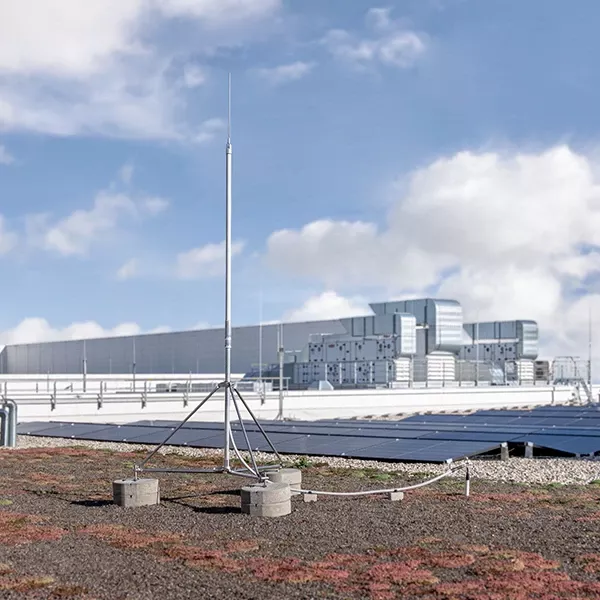
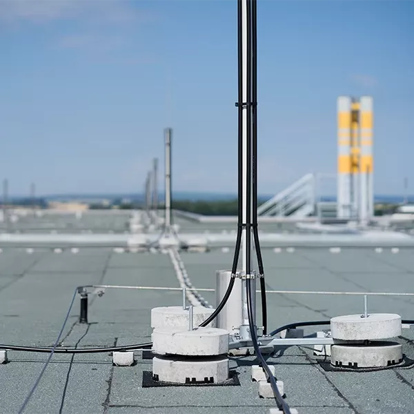
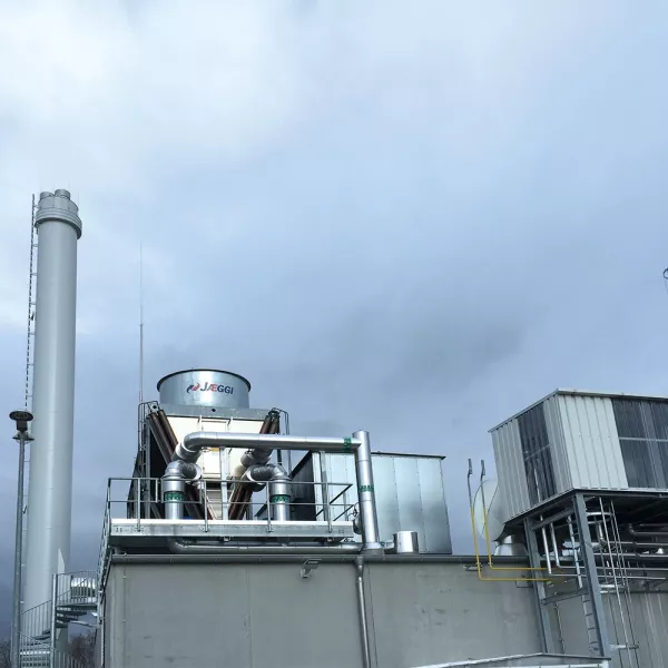
Electrically insulated lightning protection system as per IEC TS 62561-8
Our products for electrically insulated lightning protection are thoroughly tested in accordance with the IEC TS 62561-8 standard and meet the requirements for components for an electrically insulated lightning protection system. We offer you this safety both with our HVI components and with our products for the isolated air-termination system (such as DEHNiso combi sets and GRP products).
The advantages for you? Tested safety at the highest level and quality in accordance with international requirements. And not just for individual components, but for entire system solutions. HVI from DEHN – in use for you since 2003!
The available components of the HVI systems are tested as a complete system. DEHN has neither planned for nor tested the combination of our system with other components available on the market. If third-party system components are nevertheless used in the planning or installation of our HVI system, this will invalidate the warranty claim in accordance with the provision in our General Terms and Conditions and may adversely affect the functionality of the entire HVI lightning protection system.
HVI – all installation variants tested in accordance with IEC TS 62561-8
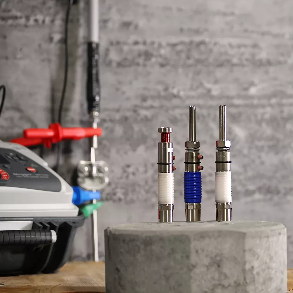
HVI Lightning Protection
HVI Lightning Protection is safe, easy and flexible to install. Before this happens, two important steps need to be taken:
Calculating wind load
The wind load is particularly important when planning and installing air-termination systems as part of a lightning protection system. Complex building structures require customised air-termination systems. Here you can find out how to calculate the wind load in five steps.
Maintaining separation distances
Maintaining the separation distance prevents dangerous flashovers between earthed parts of the building and the lightning-current-carrying components of the lightning protection system in order to avoid sparking and any associated personal injuries, property damage or fires.
Downloads
Isolated and electrically insulated lightning protection
Correct design and dimensioning
HVI light plus
The all-rounder for insulated lightning protection
HVI Check
Dielectric withstand test for HVI Conductors
Test report
HVI Lightning Protection system inspection
Creating equipotential surfaces
Formation of equipotential surfaces as a reference plane for calculating the separation distance
HVI Lightning Protection
Separation distances: simple planning, simple implementation
Our services
We can provide support for your project from the planning to the implementation and beyond. Take advantage of our wide range of practical tools and services.
Design the external lightning protection and earthing systems for your project in accordance with DIN 18014 and IEC 62305-3. The program automatically creates a bill of materials for further use.
We create the entire lightning protection concept – from the risk analysis and earthing simulation to budget planning – all precisely tailored to your project, and standards-compliant.
Use the DEHNacademy to keep you and your team up to date as well!
Get an overview of our range of courses now.
FAQ – HVI Lightning Protection systems (planning, installation, operation)
The HVI (High Voltage Insulated) Lightning Protection system uses specially insulated conductors to ensure that the required separation distance is safely maintained. This means that conductive parts of a structure do not come into contact with lightning currents – crucial protection for buildings, PV systems or technical superstructures.
The main advantage of an HVI system is its compact and secure cable routing, which requires no additional spacers or complex structural modifications. This allows cables to be neatly routed along façades or technical installations, while ensuring safety at all times.
Important to know: The insulation provides reliable protection against direct contact, but potential inductive coupling must still be taken into account.
DEHN's HVI Conductors can significantly reduce structural conflicts, as the separation distance is already integrated along the entire length of the conductor. This results in fewer roof and façade penetrations, and it makes installation simpler. The grey HVI Conductor also offers touch voltage protection, which improves safety for people in high-traffic areas. Nevertheless, the safety instructions to avoid step voltages in the earthing area should be followed.
Overall, using HVI leads to simpler planning, less coordination work and faster, standard-compliant installation – particularly for components with a metallic earth connection, such as PV frames, air-conditioning systems or railings.
Grey HVI Conductor:
- An additional outer sheath provides protection against mechanical interference
- Can be painted over (in line with installation instructions)
- Can be installed in walls and in the ground up to 2 metres deep
- UV-stable and weather-resistant
- Self-extinguishing (fire class Eca)
- Offers touch voltage protection (note additional safety instructions)
Black HVI Conductor:
- Underground installation not permitted
- No touch voltage protection
- UV-stable and weather-resistant
- Not self-extinguishing (fire class Eca)
The connection is permitted provided that the sealing end range is maintained. This area must be free of metal parts. Special case: If the separation distance at the connection is s < 17.5 cm (where
km=1), the sealing end range can be disregarded and the equipotential bonding connection is not required. If the distances are greater, the sealing end range must be fully maintained.
- HVI light plus can be used as a substitute for HVI light (when s ≤ 45 cm).
- Conductor holders are approved for HVI light plus and HVI (black/grey) (support 20–23 mm).
- Combinations with third-party components are not permitted (see Q16).
- As a general rule, the equipotential bonding should be connected to the supporting tube.
- Exceptions (HVI light plus):
- D50 supporting tubes: no EB required
- D40 supporting tubes: no EB required if s ≤ 45 cm
- When combining HVI and conventional lightning protection: EB required; not required at the connection if s ≤ 17.5 cm
- At the lower connection element (earth entry): no EB required, but possible
- HVI light plus: 105 674, 105 675, 819 674, 819 675 Note: short 1,600-mm tubes are not suitable.
- HVI / HVI power: All supporting tubes without a side outlet
- Note: Supporting tubes with a side outlet are permitted. For wall mounting, the outlet should face the wall to remain visually unobtrusive.
The sealing end range is the safety-critical transition zone at the conductor end. It can be considered as a cylinder around the connection point, the radius of which corresponds to the required separation distance s. No metallic parts may be present within this area. Special case: if s < 17.5 cm at the connection point, the area is negligible and no additional equipotential bonding is required in this zone.
The minimum bending radius is outer diameter × 10. Bends that are too tight can damage the insulation of the HVI Conductors and impair their tested impulse withstand voltage. In the event of faults, the cable route must be re-routed, bracket spacings adjusted and sharp edges avoided. Once the correction has been made, a visual inspection with photographic documentation is recommended.
Parallel cable routing can cause magnetic interference. A minimum clearance of > 200 mm must be maintained between HVI Conductors from the supporting tube outlet. Equipotential bonding conductors should not be routed in parallel with other cables carrying lightning current. Where this is unavoidable, distances should be maximised and crossings should be designed to be at right angles.
- Continuous operation: -30 to +70°C (grey: -45 to +70°C)
- Processing: -5°C to +40°C
- Heat-shrinkable sleeve up to max. 150°C[Textumbruch]Temperatures outside these ranges may result in leaks or damage to the material. Storage and construction site climates must be considered.
- Experience shows that it is preferable to work at temperatures above 5°C when processing and laying.
Yes. Spanning cables with HVI Conductors are permitted with a span length of up to 10 metres, subject to wind load verification. Longer span lengths have not been tested and not permitted, or require additional structural measures.
The HVI power Conductor can be installed outside the supporting tube, for example with connection kit 819149, but only on GRP/aluminium supporting tubes.
No. Combination with third-party products is not intended and has not been tested. This may impair functionality and invalidate the warranty.
All HVI conductors have Ex zone approvals (manufacturer's declaration) for use in potentially explosive atmospheres of zones 1 and 2 (gas zones) and zones 21 and 22 (dust zones).
Zones 1 and 21:
- HVI light plus, HVI and HVI power permitted
- Air-termination system outside the zone
- Lightning channel must not cross the zone
Zones 2 and 22: No restrictions.
Yes. DIN EN IEC 62305-3 permits the use of other materials provided that they have equivalent mechanical and electrical properties. HVI Conductors are tested in accordance with DIN IEC/TS 62561-8.
All HVI system components have been tested in accordance with DIN IEC/TS 62561-8, including corrosion and UV tests.
- HVI / HVI light plus: up to 5 conductors (1× inside, 4× outside)
- HVI power (aluminium): 2 down conductors (1× inside, 1× outside) with connection kit 819149
- HVI power stainless steel versions: 1 down conductor
The summary of a test is referred to as the test report. Where necessary, this may include the following:
- General information such as the owner, year of construction and manufacturer of the lightning protection system.
- Information about the design, use, protection class, operating location, roof covering, etc.
- Information about the lightning protection system (e.g. separation distance).
- Basis of the testing (e.g. regulatory requirements).
- Type of testing (e: complete inspection).
- Test result (e.g. deviations from the current standards).
- Name of the inspector / testing organisation.
With an electrically insulated HVI system, an equivalent separation distance 's' can be maintained along the cable route. This eliminates the need for many individual 's' distance verifications and reduces structural conflicts, particularly with earthed metallic components such as PV systems, AC units or metal façades. More compact routes, fewer spacers and fewer penetrations make planning and installation simpler and reduce the amount of reworking required – a clear advantage in terms of total cost of ownership (TCO) and acceptance.